Summary
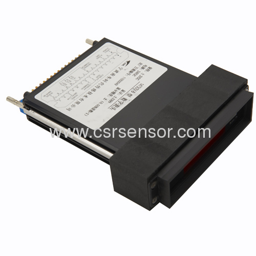
ZDZ1 multifunctional gauge combination module is composed of double-pointer speed gauge, slot-type ammeter, state indicator light, emergency brake button, signal transmission cable. Installed in the control console, it is an important set, showing train operating parameters, equipment operation state, and other related information. Depending on the combined module structure, it is endowed with the following advantages: convenient installation, visual display, integral beatification, good reliability.
Function
1. Measure and display the instant speed and limited speed of running locomotive.
2. Measure important operation parameters of locomotive. (See appendix)
3. Display the operation state of equipment in locomotive. (See appendix)
4. Electric locomotive have emergency brake button, while diesel locomotive don't.
Technical Parameter of Gauge Module
The technical parameter of gauge module is composed of three separate technical parameters of double-pointer speed gauge, slot-type ammeter, and state indicator.
1. Technical parameter of double-pointer speed gauge for locomotive
a) Measuring range:Depend on the type of locomotive
b) Input signal:0~20mA(DC)
c) Accuracy:Grade 1.5
d) Applicable environment:-25℃~+50℃,Relative humidity ≤ 95%
e) Insulation resistance:≥5MΩ
f) Lighting voltage:Electric locomotive DC24V±20%;Diesel locomotive DC110V±20%
g) Damping:≤4S
2. Technical parameter of slot-type ammeter for locomotive
a) Measuring range and the red line position:Depend on the type of locomotive
b) Accuracy:Grade 1.5,Secondary gauge with sensor: Grade 2.5
c) Applicable environment:-25℃~+50℃,Relative humidity ≤ 95%
d) Insulation resistance:≥5MΩ
e) Lighting voltage:Electric locomotive DC24V±20%;Diesel locomotive DC110V±20%
f) Damping:≤4S
3. Technical parameter of state indictor
a) State indicator light: LED Supply voltage:15V,Max. lighting strength: ≥8mcd
b) Power supply of module:DC15V±20%,or DC24V±20%,or DC110V±20% (See appendix)
c) Signal voltage:DC15V±20%,or DC24V±20%,or DC110V±20% (See appendix)
d) Applicable environment:-25℃~+50℃,Relative humidity ≤ 95%
e) Insulation resistance:≥5MΩ
Connection and Definition of socket connector see diagram 1
Diagram 1
1. State indicator and its corresponding socket (48-Pin) pin No. (See diagram 2)
Diagram 2
Brightness | 2d | 4d | 6d | 8d | 10d | 12d | 14d | 16d | 18d | 20d | 22d | 24d |
Brightness | 2z | 4z | 6z | 8z | 10z | 12z | 14z | 16z | 18z | 20z | 22z | 24z |
a) 26d\28d\30d Emergency brake normal open point (See appendix)
b) 26z\28z Emergency brake normal close point (See appendix)
c) 32D Power supply +DC(See appendix)
d) 32Z Power supply -DC(See appendix)
2. State indicator color and definition:Depend on the type of locomotive
3. Connection of slot-type ammeter for locomotive in module (See diagram 3)
Module lighting connection:Gauge module lighting terminal "9"\"10" connect with lighting power supply(Terminal 9 connect +,and terminal 10 connect -),Inner lighting wires of gauge module are parallel connected.
Diagram 3
4. Module 9-pin socket connection diagram(Double-pointer speed gauge)
Diagram 4
Installation Dimension (See diagram 5)
1. The module is installed by four direct-push screws.
2. Gauge module installation dimension:325mm×180mm
3. Gauge module outline dimension:340mm×250mm×200mm
4. Installation hole:4-Ф5.5(bolt hole)
Diagram 5
Operation method
1. Installation
Connect the ammeter terminals and connect plugs, put the gauge module into the installation hole of control console, fix the holding screws.
2. Lighting adjustment
Brightness stepless adjustment of indicator light
Brightness adjustment:When the indicator light is turned on, press the brightness button ,when the light gets brighter,leave the button and the brightness will be kept;press the brightness button,when the light gets darker,leave the button and the brightness will be kept
Brightness self-check:Press the button & at same time, the indicator light will flicker at the brightest lightness.
Brightness holding:The brightness will be kept after power-off.
Maintenance
1. When install the 48-pin and 9-pin socket, fix the locking screw tightly
2. The gauge module has the capacity of 120% overload, but the upper limit value in dial should not be exceeded.
3. Every 3~6 months the gauge module have to be checked in order to ensure the accuracy and the quality of indicator light.
4. Pay attention to dust-proof, damp-proof, and quake-proof for gauge module when not using. The module should be kept in storeroom with ambient temperature 0~40℃ and relative humidity 85%, keeping away from caustic and hazardous gas and substance. If not use the module for over three months, it should be electrified each three months in order to keep the performance of electric components during effective storage life.
Appendix
Module operation instruction is attached for indicating detailed specification and parameter of each different module.