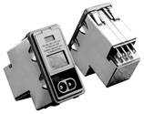
- Full flexibility of design inthe most compact package
- General purpose designed forDC applications
- Mates with a standard MOLEX*connector (HCS Series) which prevents accidental connection to AC Power
Ordering Information
Available Part Numbers

Available Part Numbers
PE000DD3D | PS000DD3D |
PE000DD6D | PS000DD6D |
PE000DDXD | PS000DDXD |
PE000SD3D | PS000SD3D |
PE000SD6D | PS000SD6D |
PE000SDXD | PS000SDXD |
Specifications
Hipot rating (oneminute): | ||
Line to Ground | 2250 VDC | |
Line to Line | 1450 VDC | |
Rated voltage(max.): | 80 VDC | |
Rated Current: | 3 to 10A | |
Fuseholder: | Accepts one or twofuses .25" x 1.25" (not included) or 5 x 20mm (notincluded) | |
Terminals: | .187 x .032 [4.8 x .81]terminal tabs | |
Recommended for usewith mating connector, no solder | ||
Operating Ambient Temperature Range(at rated current Ir): | ||
-10°C to +40°C | ||
In an ambienttemperature (Ta) higher than +40°C the maximum operating current (Io) is calculated as follows: Io = Ir √(85-Ta)/45 | ||
Electrical Schematic

Case Styles
PE

PS
Recommended Panel Cutouts
PE

PS

Recommended Panel Cutouts

Note: The external edges (installation side) on the "D" sides of the cutout should have a minimum .020" radius. For optimal retention against extraction, the corresponding inner edge should be sharp, without paint or coatings. Edge coatings, including anodization are also discouraged for good shield contact.
Case Dimensions
Part No. | A | B | C | D | E | F |
(max.) | (max.) | (max.) | * see Note | * see Note | (ref.) | |
PE | 1.98 | 2.13 | 2.31 | 1.12 | 2.201 | 1.575 |
50.29 | 54.10 | 58.67 | 28.45 | 55.91 | 40.0 | |
PS | 1.24 | 2.13 | 2.31 | 1.06 | 2.201 | |
31.50 | 54.10 | 58.67 | 26.93 | 55.91 | ||
*+.008 [.201] /-.000 [.000] | ||||||
Accessories
18-12-1222: Female Terminal (2 needed per housing)

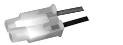
GA210 - (shown above) Pre-assembled connector housing with two 36" long 18 gauge wires to mate with P Series DC filters
MOLEX* Component Numbers:
03-12-1026: Connector housing to mate with DCP Series18-12-1222: Female Terminal (2 needed per housing)
Performance Data
Minimum Insertion Loss in dB:
Measured in closed 50 ohm system
Common Mode / Asymmetrical (Line to Ground)
Differential Mode / Symmetrical (Line to Line)
Minimum Insertion Loss in dB:
Measured in closed 50 ohm system
Common Mode / Asymmetrical (Line to Ground)
Current Rating | Frequency - MHz | ||||||||
.03 | .1 | .15 | .5 | 1 | 3 | 5 | 10 | 30 | |
3A | 7 | 17 | 21 | 27 | 33 | 40 | 44 | 50 | 32 |
6A | - | 8 | 12 | 17 | 23 | 32 | 36 | 44 | 30 |
10A | - | 3 | 5 | 10 | 13 | 23 | 27 | 35 | 27 |
Differential Mode / Symmetrical (Line to Line)
Current Rating | Frequency - MHz | ||||||||
.10 | .15 | .5 | 1 | 3 | 5 | 10 | 30 | ||
3A | 2 | 4 | 12 | 15 | 30 | 48 | 50 | 45 | |
6A | 2 | 4 | 12 | 15 | 22 | 42 | 55 | 45 | |
10A | 2 | 4 | 12 | 15 | 22 | 42 | 55 | 45 | |