ADVANTAGES:
1. Qualified Joint Supplier in Nuclear Power Plant
2. China National Standards Drafting Unit of Rubber Joint
3. 25 Years Experience
4. Easy Installation
5. Certification:ISO9001&ISO14001;SGS;BV;CE
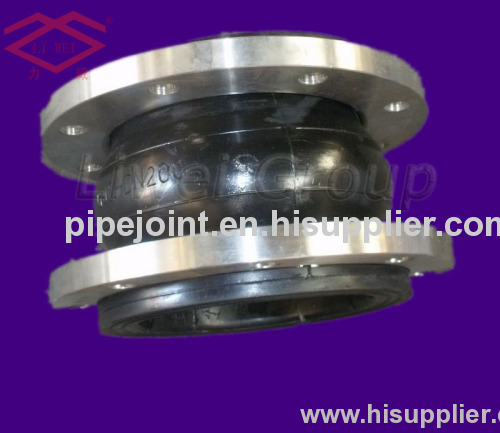
1.GJQ(X)-DF pipe fitting flexible spherical joint
| MOQ: | 1 SET |
| TRADE TERMS | FOB QINGDAO/TIANJIN/SHANGHAI OR CIF/CFR ANY DESTINATION PORT |
| CAPABILITY | 1000 SETS PER MONTH |
| DELIVERY DEADLINE | 7-40DAYS ACCORDING TO THE AMOUNT YOU BOOKED |
| PACKAGE | OUTSIDE PACKAGE: WOODEN CASE INSIDE PACKAGE: PLASTIC FILM AND TEXILE MEMBRANE WE CAN ALSO CAHNGE AS YOUR REQUEST |
2.Spherical joint introduction OF GJQ(X)-DF pipe fitting flexible spherical joint
1. This product can greatly reduce pipeline system shock and noise. And can
fundamentally resolve pipe joints displacement, axial stretch and non-concentricity.
2. By using different materials, it can be made many kinds to cater for different
medium and environment. Such as acid resistance, alkali resistance, corrosion
resistance, oil resistance and heat resistance etc.
3. The material is pure rubber, sealing is very good. It is in light weight, very easy
for installation . This product has long life performance, but must be not contact
with sharp metal instruments to avoid piercing the sphere.
4. The product can be used for lift and transportation of raw water and sewage,
transportation of water supply cooling cycle water thermal power ,condensate
water of metallurgy industry and chemical industry.
3.Classification OF GJQ(X)-DF pipe fitting flexible spherical joint
(1)according to appearence: concrentric with diameter rubber joint,concentric reducer rubber joint,eccentic reducer rubber joint.
(2)according ro the structure:single ball flexible rubber joint,double sphere rubber joint,spheres rubber joint,elbow sphere rubber joint.
(3)according to the linkthe form:flange coupling,threaded joint
(2)according ro the structure:single ball flexible rubber joint,double sphere rubber joint,spheres rubber joint,elbow sphere rubber joint.
(3)according to the linkthe form:flange coupling,threaded joint
4.Technical Parameters OF GJQ(X)-DF pipe fitting flexible spherical joint
| DN Diameter | FF Length (mm) | Axis displacement | Radial displacement | Deflexion displacement | ||||||
| Type-I | Type-II | Type-I | Type-II | Type-I | Type-II | |||||
| mm | inch | Extension | Compression | Extension | Compression | |||||
| 32 | 1¼″ | 90 | 6 | 10 | 9 | ±7.5° | ||||
| 40 | 1½″ | 95 | 7 | 10 | 9 | ±7.5° | ||||
| 50 | 2″ | 105 | 7 | 10 | 10 | ±7.5° | ||||
| 65 | 2½″ | 115 | 7 | 13 | 11 | ±7.5° | ||||
| 80 | 3″ | 135 | 8 | 15 | 12 | ±7.5° | ||||
| 100 | 4″ | 150 | 10 | 19 | 13 | ±7.5° | ||||
| 125 | 5″ | 165 | 12 | 19 | 13 | ±7.5° | ||||
| 150 | 6″ | 180 | 12 | 20 | 14 | ±7.5° | ||||
| 200 | 8″ | 210 | 16 | 25 | 30 | 35 | 22 | 25 | ±7.5° | ±10° |
| 250 | 10″ | 230 | 16 | 25 | 30 | 40 | 22 | 25 | ±7.5° | ±12° |
| 300 | 12″ | 245 | 16 | 25 | 30 | 40 | 22 | 25 | ±7.5° | ±12° |
| 350 | 14″ | 255 | 16 | 25 | 35 | 45 | 22 | 30 | ±7.5° | ±12° |
| 400 | 16″ | 255 | 16 | 25 | 35 | 45 | 22 | 30 | ±7.5° | ±12° |
| 450 | 18″ | 255 | 16 | 25 | 36 | 47 | 22 | 30 | ±7.5° | ±12° |
| 500 | 20″ | 255 | 16 | 25 | 36 | 48 | 22 | 30 | ±7.5° | ±12° |
| 600 | 24″ | 260 | 16 | 25 | 40 | 50 | 22 | 33 | ±7.5° | ±12° |
| 700 | 28″ | 260 | 16 | 25 | 40 | 55 | 22 | 33 | ±7.5° | ±12° |
| 750 | 30″ | 260 | 40 | 55 | 33 | ±12° | ||||
| 800 | 32″ | 260 | 16 | 25 | 45 | 55 | 22 | ±7.5° | ±12° | |
| 900 | 36″ | 260 | 16 | 25 | 45 | 55 | 22 | 35 | ±7.5° | ±12° |
| 1000 | 40″ | 260 | 16 | 25 | 45 | 60 | 22 | 35 | ±7.5° | ±12° |
| 1100 | 44″ | 300 | 45 | 60 | 35 | ±7.5° | ±12° | |||
| 1200 | 48″ | 300 | 16 | 25 | 50 | 60 | 24 | 38 | ±7.5° | ±10° |
| 1300 | 52″ | 300 | 50 | 60 | 38 | ±10° | ||||
| 1400 | 56″ | 350 | 50 | 70 | 40 | ±10° | ||||
| 1500 | 60″ | 350 | 60 | 70 | 40 | ±10° | ||||
| 1600 | 64″ | 350 | 18 | 25 | 60 | 70 | 24 | 46 | ±7.5° | ±10° |
| 1800 | 72″ | 400 | 18 | 25 | 60 | 75 | 24 | 48 | ±7.5° | ±10° |
| 2000 | 80″ | 450 | 70 | 75 | 50 | ±10° | ||||
| 2200 | 80″ | 400 | 70 | 75 | 50 | ±10° | ||||
| 2200 | 88″ | 500 | 70 | 80 | 60 | ±10° | ||||
| 2400 | 96″ | 500 | 80 | 80 | 60 | ±10° | ||||
| 2600 | 104″ | 500 | 85 | 80 | 60 | ±10° | ||||
| 2800 | 112″ | 550 | 85 | 80 | 60 | ±10° | ||||
| 3000 | 120″ | 550 | 85 | 80 | 60 | ±10° | ||||
Notes:
1. The size could be up to 3600mm (144").
2. The flange standard could be ANSI, GB, DIN, BS, or some other standard as per custom request.
3. The pressure is 6Mpa, 10Mpa, 16Mpa, 25Mpa.
NOTES: IF OTHER STANDARD REQUIREMENT OR SPECIAL FLANGE NEED PARTICULARLY CUSTOMER MADE, PLEASE PROVIDE WRITTEN DRAWING, STANDARD, DATA, WE CAN MAKE CUSTOMER-MADE FOR YOU.