Waterproof Round Anodized Heat Sink LED Cold Forged , Aluminum Heat Sinks
Description:
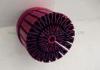
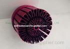
Round Cold Forged Pin Fin LED Lighting Heat Sink / Aluminum Heat Sinks has an extensive range of options to provide the optimal cooling solution for your LED application. Our precision forge process provides unique advantages for LED cooling.
- Forging can produce round and other non-linear shapes that are preferred for LED applications.
- The forge process uses high pressure to form the material and provides control over the grain structure to provide superior thermal performance.
- LED’s are generally convection cooled and our forged pin fin arrays provide the best possible thermal performance in ambient environments.
- Heat sinks can be forged in either aluminum or copper.
Applications:
LED heat sink used for all kinds of LED Lightings in Industrial area, Amplifier, Industrial, Decoration...and so on. Such as LED Street Light, LED Ceiling Light, LED Wash all Light, LED Spotlight, LED Down light, LED Ceiling Light, LED Underground Light, LED Underwater Light, LED Tunnel Light, LED Flood Light, LED Spot Light, LED Project Light, LED Hurdle Lamp, LED Industrial Light .
Specifications:
|
Base Diameter |
Ø82mm |
|
Height |
80mm |
|
Weight |
269g |
|
Base Thickness |
5mm |
After selecting or designing a heat sink based upon a given air velocity orvolumetric flow rate through the fins, the thermal designer needs to determinethe total amount of flow which must be delivered in the duct or card passagecontaining the module w with heat sink. As shown in Figure 1, some of the flowwill go around or bypass the heat sink. In fact, depending upon the free area onthe sides and above the heat sink in comparison to the flow area between thefins, a significant portion of the approaching air flow will simply bypass theheat sink. Although computational fluid dynamics codes offer a very useful toolfor analyzing flow through and around the heat sink, the methodology describedhere provides a simple technique for obtaining an initial estimate of flowbypass for use in air moving device selection and trade-off studies. Thisapproach is an extension of that originally described by Lee [1].
 Figure 1. CFD results illustrating flow velocitiesbetween fins and around the sides of a parallel plate fin heat sink
 Figure 2. Heat sink flow and bypass geometry.