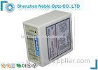
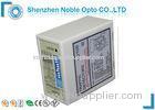
Self-turning Range Traffic Loop Detector Indicates Vehicle Detection Pulse Relay Signal
Description:
The NBT-ILD™ vehicle loop detector is compatible with most gate operators. The ULT-MVP may be used in Center, Safety and Exit loop positions.Fifteen sensitivity settings allow for fine adjustment of the detection level.
Sensitivity Selection
Sensitivity of the loop can be adjusted by the trimpot labeled “Sensitivity”. User can select 16 different setting by turning the trimpot with 0 being the least sensitive and “F” being the most sensitive.
Power Led: RED power LED indicates “Power ON”
Detecting Led: Continuously On: Indicates vehicle detection.
Blinking slowly: Indicates loop is short circuit or the number of twists after the loop is not enough.
Blinking fast: Indicates loop is open circuit or too many twists after the loop.
Loop detectors in recent years have become a popular tool having innumerable applications in policing, right from surveillance operations to traffic control. Automation of gates and doors has become a popular usage of the loop detector.
Specifications:
|
Technical Parameter for single channel vehicle detector |
Self-turning range |
20-2000μH(Q Factor >5) |
|
Response Times |
10-90MS |
|
|
Sensitivity |
16 levels,0-F |
|
|
Visual Indications |
Power LED-Red, Channel LED-Green |
|
|
ABS |
automatic sensitivity boost |
|
|
Relay time |
0,2,4,8,10,15,20,30 seconds |
|
|
Loop frequency |
4 setting(low,Med-low,Med-Hi,High) |
|
|
Operating Current |
20mA standby |
|
|
Presence time |
NORMAL/INFINITE |
|
|
Product size |
92*76*42mm |
|
|
Label Language |
English or OEM/ODM |
|
|
Connections |
Socket mount-11pin male(JEDEC B11-88) |
|
|
Storage Temperature |
-40 to 80 Celsius degree |
|
|
Normal Working Temperature |
-40 to 70 Celsius degree |
|
Detector position and installation
1. Install the detector in a weatherproof housing.
2. The detector should be as close to the sensing loop as possible.
3. The detector should always be installed away from strong magnetic fields.
4. Avoid running high voltage wires near the loop detectors.
5. Do not install the detector on vibrating objects.
6. When the control box is installed within 10 metres of the loop, normal wires can be used to
connect the control box to the loop. More than 10 metres requires the use of a 2 core shielded cable. Do not exceed 30 metres distance between control box and loop.
For USA connection:
|
Pin |
LD-105 |
LD-106 |
|
1 |
100-240V AC |
12-24VADC |
|
2 |
100-240V AC |
12-24VADC |
|
3 |
Pulse B Relay N.O |
|
|
4 |
Chassis Ground |
|
|
5 |
Presence A Relay COM |
|
|
6 |
Presence A Relay N.O |
|
|
7 |
Loop |
|
|
8 |
Loop |
|
|
9 |
Pulse B Relay COM |
|
|
10 |
Presence A Relay N.C |
|
|
11 |
Pulse B Relay N.C |
|
Troubleshooting
|
Symptoms |
Solution |
|
|
If the detector is not working |
Press reset |
|
|
If red led indicator is not fully lit |
Check for power supply |
|
|
|
Blinks slowly |
It maybe because the loop is short circuit or the no: of turns is not enough. |
|
Blinks faster |
It maybe because the loop is open or the no: of turns is too many. |
|
|
If no: of turns is not enough |
Lower the frequency (if the frequency is still too high, you must add more turns). |
|
|
If no: of turns is too many |
Higher the frequency (if the frequency is still too low, you must remove some turns). |
|
Ordering Information:
LD-100 single channel, boxed, 1 type 11pin connects 100-240VAC(EU standard)
LD-102 single channel, boxed, 1 type 11pin connects 12-24VADC(EU standard)
LD-105 single channel, boxed, 2 type 11pin connects 100-240VAC(USA standard)
LD-106 single channel, boxed, 2 type 11pin connects 12-24VADC(USA standard)
Tag:traffic loop detector,vehicle loop detector.


