Description of Impulse Safety Device
1. Use
The impulse safety device is used for power station boilers or
pressure vessels to prevent the medium pressure from exceeding the
allowable value to ensure their safety valve.
2.Characteristics
The impulse safety device works with an impulse safety valve and a main
safety valve. This device has a large discharge ability with convenient
adjustment, double mechanical and electrical protection and user-
friendly installation and maintenance.
3. Operation Principle
When the medium pressure is lower than the setting pressure, the
impulse safety valve will be enclosed under the spring force, while the
main safety valve will be enclosed under the medium pressure; when the
medium pressure is higher than the setting pressure, the impulse safety
valve will open and steam will enter into the main safety valve's
piston chamber to open the main safety valve and discharge steam to the
outside; when the pressure drops to the reseating value, the impulse
safety valve will be closed to cut off steam going into the safety
valve's piston chamber, and the main safety valve will be closed
automatically as acted by spring and the medium.
4. Structure
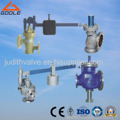
1. The impulse safety device is as shown in the figure, mainly
consisting of impulse safety valve, main safety valve, stop valve and
throttle valve.
2. The impulse safety valve is a kind of sping or heavy hammer lever.
The safety device's opening pressure can be adjusted by adjusting the
spring compression or the heavy hammer position on the lever. Also the
impulse safety valve contains an electromagnet to open or close the
valve, with no interference between mechanical and electrical actions.
3. The main safety valve is as shown in the figure. Its steam exhaust
end adopt a flange connection form, and it mainly consists of body,
cushion valve, piston chamber, disc and other parts. The valve adopts
the pressure self tightening and sealed structure. The higher the
medium pressure is, the better the sealability will be. The cushion
valve serves as a buffer in the working process of the main safety
valve to avoid the damage of the sealed surface and the disc.
4. The upper part of the impulse safety valve contains an
electromagnet to open or close. At ordinary times, the close-off
electromagnet may not be electrified, but when the sealed surface of
the valve leaks, it can be electrified continuously to make the valve
sealed; or when the mechanical adjusting reseating pressure is
excessively low, it can be electrified to help the disc return and
procure a higher reseating pressure.
5. Installation Instruction
1. The main safety valve and the impulse safety valve should be
installed together. The distance between the outlet pipe of the impulse
safety valve and the inlet pipe of the main safety valve should be
maintained as relatively long and the distance between the electric
contact pressure meter and the inlet pipe of the main safety valve
should be no less than 5 times of the diameter of the inlet pipe, of
the main safety valve should be no less than 5 times of the
diameter of the inlet pipe for fear t hat the precision of the
meter and the impulse safety valve may be affected by the
steam discharging process of the main safety valve.
2. Before the installation of the main safety valve, the pipeline
shall be cleaned first.
3. The main safety valve and the impulse safety valve must be
positioned vertically. After the installation and the welding of main
safety valve, it shall be under partial heat treatment.
4. The main safety valve shall be fastened upon the framework, which
sustains the counter-reaction force produced in the steam discharging
process of the mains safety valve. The exhaust pipe of the mains safety
valve shall be supported with a special gallow lest the force of its
weight and action would be directly apply to both the main safety valve
and the flange that is connecting them. At the lowest point of the
exhaust pipe, water drainage shall be taken into consideration to avoid
producing water hammer when the main safety valve is discharging steam.
The three loops of filling above the mains safety valve's piston
chamber shall be deeply compressed until the lower surface of the
filling gland touches the upper surface of the piston, and a fine wire
shall be used to fasten the pressure bolt to avoid leakage and refusing
release of the main safety valve.
5. The impulse safety valve and the electromagnets shall be placed
together on a special gallow. The juncture of the upper lever of the
valve and the electromagnets shall be flexible, with no phenomenon of
seizure. The impulse safety valve shall be installed in a place with
little dust, dry air and convenient maintenance and debugging and where
no vibration occurs. Its ambient temperature shall not be higher than
70 Deg C, and its relative humidity not more than 80%.
6. To ensure the agile working of the impulse safety valve, the
distance between the circular arc part of the head of the seat
returning lever and the end of the pressure bar of the valve shall be
adjusted to such a length as the actual travel of the valve plus 1mm
(adjusted by the M10 fastening screw at the top of the cap.)
Home >
Machinery & Industrial Supplies
>
General Parts
>
Valves
>
Impulse Safety (valve) Device Application/Characteristics &Operation Principle
Impulse Safety (valve) Device Application/Characteristics &Operation Principle
| Price: | 2.0 USD |
|---|---|
| Trade Term: | FOB,CFR,CIF |
| Payment Terms: | T/T,L/C,WU |
Trade on HiSupplier, Worry Free Guarantee
•Trading safety, secure your money, lower the risk, protect both buyers and suppliers
•HiSupplier is a Chinese multinational company in U.S, it helps to coordination and order landing.
- Product Details
- Company Profile
- Product Reviews
Basic Info.
- Power: Pneumatic
- Standard or Nonstandard: Others
- Media: Gas
- Pressure: Vacuum
- Material: Alloy
- Temperature of Media: High Temperature
- Structure: Ball
- Brand Name: goole
- Place of Origin: Zhejiang
- Min.Order: 10 Piece/Pieces
- Means of Transport: Ocean, Air, Land
Supply Capacity
- Production Capacity: 10000
- Packing:plywood case
- Delivery Date: 30days

Didn't find what you're looking for?
Post Buying Lead or
contact our customer service specialist for help!


