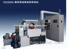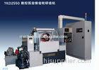


High Precision Gear Lapping Machine , 3000rpm CNC Bevel Gear Lapper Machine
Quick Detail:
This machine is a CNC bevel gear lapper designed mainly for lapping in pairs all kinds of bevel gears., especially for bevel gears manufactured by batch and mass productions used in automobile, passenger car, tractor, ship building and machine tool industries.
Along with the continuous development of the automobile industry, the application of the lapping technique becomes wider and wider. This machine is used for the high-speed and accurate lapping of spiral bevel gears and hypoid gears to increase the surface finish of the tooth flanks, to correct properly the tooth distortions produced after heat treatment and to modify the positions and size of the tooth bearings in order to attain to the goals of smooth transmission and lower noise.
Description:
1The driving shaft is mounted vertically and the force directs against the machine bed to increase the driving rigidity.
2 E, P and G (X, Y, Z) three axial additional lapping motions are adopted and concentrated upon the driven shaft. The machine structure is compact, and motions are made by lead screws driven by three servo motors and controlled by the NC system. Together with the driving shaft, simultaneous movement of three axes and various lapping cycles are possible.
3The driving shaft is driven by a servo motor of great torque, and the maximum speed is up to 3000 rpm and can be adjusted freely. Meanwhile, frequent rotations and reverse rotations can be made to lap the drive sides and the coast sides of the gear teeth. The hydraulic motor drives the driven shaft and the braking moment is controlled by an electro hydraulic proportional control valve. This solution is both up to date and reliable, and the adjustments are convenient.
4 The angle of the lapping compound swivel rod is adjustable, which has two adjustable nozzles. One is for the drive sides and other is for the coast sides.
5The MITSUBISHI M64 CNC control system and servo system are equipped on this machine. A 5.5 kw, 0-3000 rpm servo motor is used as the main drive and the E and P (X, Y) motions are driven by 1 kw, 2000 rpm motors. The G(Z) motion is driven by a 1.5kw, 2000 rpm servo motor and the relative servo unit. The main drive motor can be regulated steplessly and changes over between rotations and reverse rotations every 20 seconds to 1 minute. The swiveling amounts of E, P and G (X, Y, Z) three axes are adjustable and the three axes can move simultaneously. All the four lapping cycles (standard, center, trimming and periphery)will be controlled by the machining programs. All the buttons for the operation and adjustment necessary for the lapping cycles are mounted on the control panel and the button station. The E, P and G (X, Y, Z) coordinate values of the driving shaft and the driven shaft can be displayed on the screen.
6The braking moment of the driven shaft is controlled by the electrohydraulic proportional control valve mounted on the hydraulic system. The moment can be adjustable in the range from 2.5-25NM, and a torque displaying device is available. The hydraulic motor has the braking and shedding functions, and pressures for braking and shedding are set to 2.0Mpa and 7.0Mpa respectively. Clamping and unclamping of workpieces on the driving and driven shafts, the advance and withdrawal of the driven stock, clamping and unclamping of the driven stock and the cross slide, swiveling in and out of the lapping compound rod, and the opening and closing of the enclosure can be done through different hydraulic cylinders. The hydraulic oil is cooled by an independent cooling system.
7The air sealing of the driving and driven shafts, the blowing for cleaning the arbor of the driven gear, the pneumatic position detection of the driven stock, the pneumatic position detection of the lapping compound rod to the up position and control of opening and closing of the right and left lapping compound nozzles will be conducted by the pneumatic system.
8The machine has an independent system to heat, mix and supply the lapping compound.
9A safety enclosure is equipped on the machine.
10An air conditioner can be equipped for the independent sealed electrical cabinet.
Specifications:
|
Maximum Diameter of Driven Gear |
mm |
500 |
|
|
Maximum Diameter of Driving Gear |
mm |
250 |
|
|
Maximum Offset |
mm |
±76 |
|
|
Distance from Spindle Axis of Driving Stock to Spindle of Nose of Driven Stock |
mm |
114~191 |
|
|
Distance from Spindle axis of Driven Stock to Spindle Nose of Driving Stock |
mm |
165~305 |
|
|
Driving Spindle |
|||
|
Diameter of Spindle Hole at Large End |
mm |
100 |
|
|
Taper |
|
1:20 |
|
|
Taper Depth |
mm |
150 |
|
|
Diameter of through Hole |
mm |
92.5
Channel: madeinchina.hisupplier.com - hebei.hisupplier.com - ningbo.hisupplier.com Language Option:
العربية -
Nederlands-
Français-
Deutsch-
Italiano-
日本語-
한국의-
Português-
Pусский-
Español
IPR Protection Policy -
Terms of Use -
Privacy Policy -
Security Measures
Copyright © HiSupplier.com Online Inc. All Rights Reserved. | |