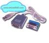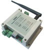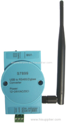
S7899 is USB to RS485 converter and USB to Zigbee converter, through jumper select it. Get power from USB port and do not need extra power supply.
In both way, the converter handle data transparent.
Rs485: Just need install USB driver, do not need further configuration.
According to user requirement, we can provide isolated or non-isolated RS485.
Zigbee: Except driver, also need config the zigbee module, details in below.
1. Technical Parameters
Name | Technical Data |
Transmission Distance | 100 meters ~ 3,000 meters |
Network Topology | Star, tree and chain type, mesh network |
Network ID | 0~255 |
Network Node | 0~65535 |
Maximum Packets | 256 bytes |
Data Interface | USB |
Serial Rate | 1200 ~ 115200 bps |
Modulation Mode | DSSS direct sequence spread spectrum |
Frequency Range | 2.405GHz~ 2.480GHz |
A Radio Channel | 16 |
Receiving Sensitivity | -94 dbm |
Transmission Power | -27dBm~25dBm |
Antenna | External SMA Antenna |
Conflict Prevention | GTS, CSMA - CA and CSMA - CA |
Input Voltage | 5V,get from USB BUS9 |
Power consumption | 22mA@24VDC |
Operation tempearture | -40~85℃ |
Storage temperature | -40~125℃ |
2.Connection definition
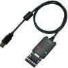
A. USB Data Interface
It i s standard USB interface, compatible USB 2.0
The signal sequence is:
Vcc, 5V power supply for the board
UD+
UD-
GND
Can run operating system windows 98/ME/2000/XP/Server 2003/VISTA/Server 2008/Win7 32bit/64bit
B. Configuration Interface
If you need config the Zigbee module, please follow these steps to enter configuration mode.
Press the CONFIG button for 3 seconds when power is on, the system will go to configuration mode.
The flashing of ALARM and RUN LEDs means that the system is going to configuration mode. The configuration interface is USB.
Default Setting of Interface:
Serial Port Parameters | Default Settings |
Serial Rate | 38400 |
Serial Check | None |
Data Bits | 8 |
Stop Bits | 1 |
3. Module MAC_ADDR Address & Module Type
Module MAC_ADDR Address Settings:
MAC_ADR Options | ID range | Configuration | Note |
MAC_ADDR | 0000—FFFE | Center module address: 0000 | Unique address in the same network. |
Module Type Seetings:
TYPE Options | Network Type | Configuration | Note |
PAN_Coord | Center Module | There must be only one center node in network | |
ROUTER | Router Module | Can replace terminal device deModuleeequipment function. | |
END_DEVICE | Terminal Module |
S7889 Zigbee wireless communication module has three Module types: the central Module, the router Module and terminal Module. Each type can be set by jumpers or user's MCU according to user design.
4. Signal Channel Settings
Channel | Description | Notes |
0-F | 0 : 2.405GHz 1 : 2.410GHz 2 : 2.415GHz 3 : 2.420GHz 4 : 2.425GHz 5 : 2.430GHz 6 : 2.435GHz 7 : 2.440GHz 8 : 2.445GHz 9 : 2.450GHz A : 2.455GHz B : 2.460GHz C : 2.465GHz D : 2.470GHz E : 2.475GHz F : 2.480GHz | Channel4, 9, 14, 15 are recommended, which can avoid WIFI interference. |
0x10 | AUTO mode, choose the best channel. |
5. Network Type & Network ID
Network Type Settings:
NET_TYPE Options | Network Type | Configuration | Notes |
MESH | Mesh network | In master-slave network, must have unique center node. | In a network, the network type must be the same |
STAR | Star nets | ||
LINE_1 | Chain type nets ID=1 | ||
LINE_2 | Chain type nets ID=2 | ||
LINE_3 | Chain type nets ID=3 | ||
LINE_4 | Chain type nets ID=4 | ||
PEER | Peer-to-peer network | Not master-slave nets, no center module. |
Network ID Settings:
Options | ID Range | Configuration | Notes |
NET_ID | 00—FF | In one network must have unique network ID. |
6. Tansfer Type Mode & Data Type
TX Type Mode Settings:
TX_TYPE options | Send mode | Configuration | Note |
BROADCAST | Broadcast mode | No target address. | Target address is 2 bytes MAC address, the first two bytes in a data package. |
MASTER—SLAVE | Master-slave mode | For center Module must be assigned target address before sending it out. For not center Module, then no need to assign target address because target module is center Module, it is default. | |
POINT—POINT | peer-to-peer | Target address must assign for both direction. |
Data Type Settings:
DATA_TYPEoptions | Data types | Configuration |
ASCII | ASCII | Only in the target address situations settings, in broadcast cases do not need setting. |
HEX | Hex |
7. Serial Port Settings
Data Bit Settings:
DATA_TYPE Options | Data Types | Configuration |
7+1+1 | 7 data bits +1parity check bit + 1 stop bit | Choose them together with Data Parity Setting. |
8+0+1 | 8 data bits +0 parity check bit + 1 stop bit | |
8+1+1 | 8 data bits +1parity check bit + 1 stop bit |
Serial Port Baudrate Settings:
BAUD_RATE Options | Baud rate scope | Configuration |
1200~115200 | 1200~115200 | Choose the right baudrate. |
Data Parity Settings:
DATA_PARITY Options | Module types | Configuration |
NONE | None | Choose the right Data Parity. |
EVEN | Even check | |
ODD | Odd check |
Serial Port Time-out Settings:
TIME-OUT Options | Module types | Notes |
TIME_OUT | 1-255ms(Hexadecimal display) | Serial overtime time. |
8. Data SRC Address Settings
SRC_ADRoptions | Source address | Configuration |
NO OUTPUT | Don't output source address | To decide if choose to output the source address in data packet according to application.. |
HEX | Hexadecimal output | |
ASCII | ASCII output |
Hexadecimal way output source address formats: 2 bytes of data source address + data package,
ASCII mode output source address formats: 4 bytes of data source address + data package.
9. Data Transmission Instructions
Data Transmission Mode:
Module type | Send mode | Target Module | Data Format |
Center Module | Broadcast | All Module except center Module | Data transfer directly |
Master-slave or peer-to-peer | Target address Module | Target address + data package | |
Not center Module | broadcast | All Module except center Module | Data transfer directly |
Master-slave | Center Module | Data transfer directly | |
peer-to-peer | Target address Module | Target address + data package |
Data Format Mode:
Send mode | Data coding | Data frame format |
Data transfer directly | Do not need any changes | |
Target address + data package | Hexadecimal target address | 2 bytes target address + data package |
ASCII target address | 4 bytes target address + data package |
10. LED Indication
LEDs | Status | Description |
Data | ON | Work properly |
OFF | Cut off power | |
Running | Flashing at 1 second interval | System runs normally |
OFF | Module is not running, no power or burned out | |
Network | ON | Center node set success, other Module have joined network |
OFF | Not connected to network | |
Alarm | OFF | Work properly |
ON | Abnormal or enter special system status |
11. Configuration command
All Command and parameters are Hexadecimal.
Do the following step to enter configuration mode:
First,put CONFIG pin to low level more than 3 seconds
Second,set serial port as 38400,8,N,1
A,Get module configuration parameters command
23 A0
B,Response data for command 23 A0
A2 +14 bytes data
Format for 14 bytes data:
The first 2 bytes are module address.
The third byte is net ID,range of ID is 00 - FF.
The fourth byte is net type,01 = mesh netork,02 = star network,07 = peer to peer network.
The fifth byte is module type,01 = center module,03 = router module,04 = terminal module.
The sixth byte is transfer mode,01 = broadcast,02 = master-slave,03 = peer to peer.
The seventh byte is baudrate.01= 1200,
02 = 2400
03 = 4800
04 = 9600
05 = 19200
06 = 38400
The eighth byte is parity check,01 = none,02 = EVEN,03 = odd.
The nineth byte is data bit,01 = 8-bit,03 = 9-bit.
The tenth byte is data format,01 = ASCII,02 = HEX.
The eleventh byte is serial port timeout.1-255ms.
The twelfth byte is signal channel,0 to 15,recommend 4,9,14,15.
The thirteenth is transfer power.
The fourteenth byte is if output source address,01 = not output ,02 = ASCII format output,03 = HEX format output.
C,Set module configuration parameters command
23 FE + 14 bytes configuation data
D,Configure remotely
23 CA xx xx (2 byte target address,fill FF FF if change all network)
For example,fix net ID and signal channel:
23 CA FF FF FF FF ID FF FF FF FF FF FF FF FF CHANNEL FF FF
E,Quit configuration
Must put high level for CONFIG pin.
23 23
The module wil restart and enter normal work mode.
F,Steps for configuration:
A,Get module configuration data,23 A0
B,Copy 14 bytes data you get,get rif of the first byte A2.
C,Change the corresponding parameters
D,Add 23 FE at the latest 14 data then send to module.
E,Restart the moduel.
The default configuration parameters command is:
Master: 23 FE xx xx FF 02 04 02 05 01 01 02 0A 0F 00 01
Slave: 23 FE xx xx FF 02 01 01 05 01 01 02 0A 0F 00 01
Xx xx different according to different modules, it is module address, range from 0 to 65535