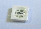
Infrared led light emitting diode 3 Chips in One 0.2W SMD 5050 IR LED 940nm
SMD 5050 Infrared Emitting Diode
- Applications:
- The TOP5050 is available in soft red, orange, yellow, green, blue and white. Due to the Package design, the LED has wide viewing angle and optimized light coupling by inter reflector, this feature makes the SMT TOP LED ideal for light pipe Application. The low current requirement makes this device ideal for portable equipment or any other application where power is at a premium.
-
- Descriptions:
- P-LCC-6 package.
- White package.
- Optical indicator.
- Colorless clear window.
- Ideal for backlight and light pipe application.
- Inter reflector.
- Wide viewing angle.
- Suitable for vapor-phase reflow, infrared reflow and wave solder processes.
- Suitable for all SMT assembly and solder process.
- Computable with automatic placement equipment.
- Available on tape and reel (12mm Tape).
- The product itself will remain within RoHS compliant Version.
-
- Descriptions:
- Package in 8mm tape on 7” diameter reel.
- P-LCC-6 package.
- White package.
- Optical indicator.
- Colorless clear window.
- Low forward voltage.
- Wide viewing angle.
- Suitable for automatic placement equipment.
- Suitable for vapor-phase reflow, infrared reflow solder processes.
- The product itself will remain within RoHS compliant Version.
- Absolute Maximum Ratings at Ta=25
| Parameters | Symbol | Max. | Unit |
| Power Dissipation | PD | 130 | mW |
|
Peak Forward Current (1/10 Duty Cycle, 0.1ms Pulse Width) |
IFP | 1.00 | A |
| Continuous Forward Current | IF | 65 | mA |
| Reverse Voltage | VR | 5 | V |
| Operating Temperature Range | Topr | -25 to +80 | |
| Storage Temperature Range | Tstg | -40 to +85 | |
| Soldering Temperature | Tsld | 260 for 5 Seconds | |
Electrical Optical Characteristics at Ta=25
| Parameters | Symbol | Min. | Typ. | Max. | Unit | Test Condition |
| Radiant Intensity * | Ee | 1.00 | 1.50 | --- | mW/sr | IF=20mA |
| --- | 7.00 | --- |
IF=100mA (Pulse Width≤100µs, Duty≤1%) |
|||
| Viewing Angle * | 2θ 1/2 | --- | 120 | --- | Deg | IF=20mA (Note 2) |
| Peak Emission Wavelength | λp | --- | 940 | --- | nm | IF=20mA (Note 3) |
| Spectral Bandwidth | λ | --- | 45 | --- | nm | IF=20mA |
| Forward Voltage | VF | 0.80 | 1.20 | 1.50 | V | IF=20mA |
| --- | 1.40 | 1.80 |
IF=100mA (Pulse Width≤100µs, Duty≤1%) |
|||
| Reverse Current | IR | --- | --- | 10 | µA | VR=5V |
Notes:
Luminous (Radiant) Intensity Measurement allowance is ± 10%. θ1/2 is the off-axis angle at which the luminous intensity is half the axial luminous intensity. The dominant wavelength (λp) is derived from the CIE chromaticity diagram and represents the single wavelength which defines the color of the device.
Infrared Emitting Diode Package Dimension: