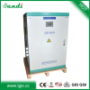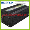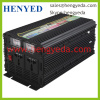
Product Name:2500W solar stackable power inverter
Security features:
There are full protection and audio-visual alarm system in SUN-1500P power inverter. It can provide a full range of protection, mainly over-voltage protection, low-voltage alarm, under-voltage protection, over-heat protection, overload protection, short circuit protection, reverse polarity protection etc.
Protection and alarm sound definition:
.Low-voltage alarm: When the input DC voltage is lower than low-voltage alarm voltage, low battery alarm will remind the user that there is less power, but the power inverter can still continue to work. The alarm sound is the long sound "beep --- beep ... ...."
. Under-voltage protection: When the input DC voltage is lower than the cut off under-voltage, the power inverter output will be cut off automatically .Sound alarms "beep-beep-beep --- beep- beep-beep ... ...." When the input voltage returned to the normal input voltage, the inverter will restart output automatically. If the input voltage immediately returned to normal after alarm, the alarm sound will continue to sound about 30S and then restart the output.
. Over-voltage protection: When the input DC voltage is higher than the cut off over-voltage, the power inverter output will be cut off automatically. Sound alarms "beep-beep-beep --- beep- beep-beep ... ...." When the input voltage returned to the normal input voltage range, the inverter will restart output automatically. If the input voltage immediately returned to normal after the alarm, the alarm sound will continue to sound about 30S and then restart the output.
. Over-heat protection: When the internal temperature of power inverter is too high (above about 85℃), the power inverter output will be cut off automatically. Sound alarms "beep-beep-beep-beep--- beep-beep-beep-beep ... ...." Need to restart manually.
. Overload protection: When the power of electric apparatus which are driven by the power inverter exceeds the inverter's maximum output, the output would be cut off automatically. Sound alarm "beep-beep---beep-beep ... ...." Need to restart manually.
.Short-circuit protection: When the output short-circuited, or the loads are very big, the power inverter output will be cut off automatically. Sound alarms "beep-beep-beep-beep-beep---beep-beep-beep-beep-beep... ...." Need to restart manually.
. Reverse polarity protection: When the input positive and negative pole of the power inverter was connected reversed, it will fuse down the inverter's fuses to protect the internal circuits. After the replacement of fuses, inverter can work properly.
Working environment
1.Operation temperature: -10℃~40℃.
2.Storage temperature: -40℃~65℃.
3.Considerable air humidity should be less than 85%.
4.No electrical conductivity, dust explosion, corrosion-free gas in the working place.
No shock and vibration in the working place.
Physical properties:
A.G.W.:6.0kgs
B.Size: 352 mm *233 mm *90 mm
Specification(@20 °C)
DF-SUN 2500P/12-230 | DF-SUN 2500P/24-230 | DF-SUN 2500P/48-230 | DF-SUN 2500P/12-120 | DF-SUN 2500P/24-120 | DF-SUN 2500P/48-120 | |
Output Continuous Max. Power | 2500W | |||||
Output Surge Power | 5000W | |||||
Converting Max. Efficiency | >88% | >90% | >92% | >88% | >90% | >92% |
Normal Input Voltage | DC12V | DC24V | DC48V | DC12V | DC24V | DC48V |
Input Voltage Range | DC10~15V | DC20~30V | DC40~60V | DC10~15V | DC20~30V | DC40~60V |
Output Voltage | AC230±5% | AC120±5% | ||||
Output Frequency | 50Hz | 60Hz | ||||
Output Wave Form | Modified Sine Wave | |||||
No load Current(Average) | <0.20A | <0.15A | <0.12A | <0.20A | <0.15A | <0.12A |
Input Low-Voltage Alarm Voltage | 10.5±0.5V | 21±0.5V | 42±1V | 10.5±0.5V | 21±0.5V | 42±1V |
Input Under-voltage Cut Off Voltage | 10±0.5V | 20±0.5V | 40±1V | 10±0.5V | 20±0.5V | 40±1V |
Input Over-voltage Cut Off Voltage | 15±0.5V | 30±0.5V | 60±1V | 15±0.5V | 30±0.5V | 60±1V |
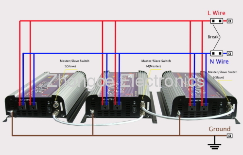
Pic.1, Sketch map of inverters connection in a parallel system
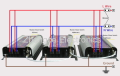
Pic.2, Frame picture of stackable inverter
Introduction
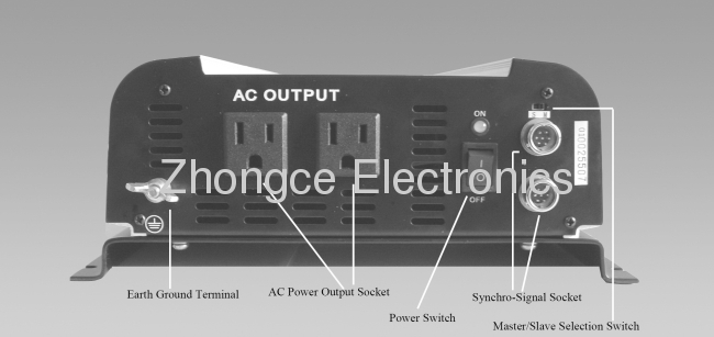
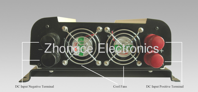
Each of this kind of inverters is complete functional inverter, but not module, and the frame of each inverter is completely same. It can be used parallel, and also can be used singly. The stackable quantities in one system can be composed freely in the range of 10pcs. In a system, when it is working, the master inverter must be power on, and the working quantities of the other slave inverters depend on the usage of the load. So it's very convenient to use and can maximum reduce the power loss of no load in the system. The cost of stackable power inverter is close to the cost of the same kind of common inverter. At present there is also module stackable inverter in the market and it's the cabinet combination. But usually the module can't be used singly and the combination is not very freely. The pic.1 is sketch map of inverter parallel connection, in it, 1 is the master inverter of the parallel inverter system, 2 and 3 are the slave inverters. There are must and only one master inverter in one system. The master inverter is complete the same as the slave inverter. Which one is master and which one is slave, it depends on the choosing switch on the inverter panel. In the system, the 'Syn' of each inverter are all hanged on bus of single line synchronization. The L wire of AC output connected with L wire, N wire of AC output connected with N wire each other. But the negative terminal of each DC input need to be connected with a lead, the positive terminal can be detached and also can be connected. So in the system, different DC power supply power to different inverters, as well as the same DC power supply power to all the inverters, it can be used very flexible. Because there are synchronous signal cut-off detection, many master inverters setup error detection, L wire and N wire connected error detection in parallel system, so in the progress of the system connecting, installing and debugging, it assure that the equipment can't be damaged because of the factitious errors.
Pic.2 is the frame picture of stackable inverter,1 is MCU, it's the controlling core of inverter, collecting various information which are detected and controlling various information signals; 2 is modified sine wave generator, inverting DC power to AC power; 3 is protector circuit, when the inverter was used in unusual conditions, it can protect the inverter from being damaged; 4 is high voltage detector, according to the magnitude of high DC power voltage, MCU adjusts the impulse width of output AC power automatic, assures the virtual value fixed at some ranges; 5 is high voltage generator, inverting the input DC low voltage power to DC high voltage power through high frequency commutation. 6 is N/L wire detector, detecting whether the output N/L of various inverters connected congruously or not in the system; 7 is input voltage detector, detecting whether the voltage of input DC power is in the prescriptive range or not; 8 is short circuit detector, detecting whether the output port is short circuit or not; 9 is temperature detector, detecting the working temperature of inverter; 10 is overload detector, detecting whether the output power of inverter exceed the rating or not; 11 is alarm circuit, expressing different fault conditions with different sounds; 12 is master/slave detector, detecting the inverter worked with master mode or slave mode; 13 is synchronization signal transmitter/receiver, when the inverter worked with the master mode, sending the synchronous signals, when the inverter worked with the slave mode, receiving the synchronous signals; 14 is power balancer, making the inverter output power which is in the working of parallel system balanced. Signal is produced by master inverter and received by slave inverter.
Appliance connection (use as parallel one)
1.The operation must be carried out in accordance with the requirements as following, or it may damage inverters in the parallel system.
2.In the system, choose any one as a master, put the master/slave selection switch on the panel to the master position, other inverters must be set as slaves, put the master/slave selection switch on the panel to the slave position.
3.First of all, switch off all inverters in the system, connect the signal lines and power lines, please pay attention to connecting the output power cord L with L lines, N with N lines as the picture 1.
4.Shut down all loads which are connected with the system.
5.If there are many DC powers (or batteries), must ensure that the negative terminal of DC powers (or batteries) must be reliably connected each other, and the positive terminal can be connected each other or not, but connected is better, as the picture 1.
6.To connect DC input wires to the DC power, please note that positive and negative polarity can not be wrong then.
7.When the above-mentioned operation is confirm correct, first switch on all slave inverters, then switch on the master, at this time there is a voltage output. Then you can use electric loads.
8.At work, how many slaver need to be on, according to the required power of the loads. However, the master must be on.
9.In the course of their work, when the protection program is active, according to the different instructions of protection (based on sound alarm judging), to make the deal. For the fault that need restart inverters manually, please cut off the connecting load before troubleshooting.
If you want to increase inverter to or remove inverter from the parallel system, you must switch off all loads which are linked to the system, and then all of the inverter switches are hit off position. To increase the inverters to the parallel system, first of all, switch off all inverters, and then connect the increased inverter's signal line and power cord to the system, do steps 1 to 9. To remove power inverter from the system, first switch off all inverters, while you want to remove the inverter, firstly, removed the output power line, and then remove the signal from the system, and then disconnect the connected DC input line. When the above-mentioned operation to confirm correct, switch on all inverters, then at this time there is a voltage output, and then you can use electric loads.


Security features
1.Synchronization signals interruption or error protection: When a slave to receive the synchronization signal interruption or error, the slave will immediately cut off the output and alarm, alarm sound is "beep---beep ... ..." It will not affect the other inverters of the normal work in the system except making other inverters to increase output power. After a period of time, the slave will detect the signals again, when the synchronization signal is normal, it will restart output.
2.Masters quantity above 2 error protections: When there's more than one inverter which is set to master, then the system power-on, the latter master will alarm, and cut off its output. Sound alarm "beep---beep ... ...." After corrected, you need to restart it manually.
3.N/L wrong protection: When the slave of each inverter detected the N/L connect wrong in the system, it will alarm and cut off its output. Sound alarm "beep-beep-beep-beep-beep-beep--- beep-beep-beep-beep-beep-beep... ...." After about 40S, it will re-detect, if normal, restart output automatically. The slave inverters just detect this error at the first time when they power on every times, when normally working, they will not detect again.