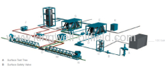
Surface well testing
Flowhead - Surface Test Tree
Emergency ShutDown (ESD) System
Choke Manifold
Data Header
3-Phase Test Separator
Vertical Surge Tank
Atmospheric Gauge Tank
Oil and Gas Manifold
Crude Oil Transfer Pumps
Burner Boom
Air Driven Chemical Injection Pump
Steam Heat Exchanger
Containerized Steam Generator
Surface Well Testing
Well Testing Equipment
Well testing equipment are designed for surface oil and gas well testing, in accordance with following codes:
ASME Section VIII, Div. 1, Latest Revision and Addenda
ASME/ANSI B16.5
ANSI B31.3
ANSI/AWS D1.1
API Spec. 6A, 6D and 16C
NACE MR.0175 Latest Edition
GB150-1998 Steel pressure vessels
GB/T8163-1999 Seamless steel tubes for liquid service
GB3836.10 ~ 3836.12-91 Electrical apparatus for explosive atmospheres
JB4726-2000 Carbon and low-alloy steel forgings for pressure vessels
HG20581-1998 Specification for materials selected of steel chemical vessels
SY/T0059-1999 Control steel equipment weld strength preventing sulfide stress crack technique specification
JB4708-2000 Welding procedure qualification for steel pressure vessels
JB4730-2005 Nondestructive testing technique for pressure vessels
JB/T 4711-2003 Coatings and transportation packages for pressure vessels
Well testing equipment supplied are safe, reliable, accurate, durable and high cost performance. They are being in service 24x7 hours in South Asia, Middle East, Africa and Chinese Mainland by Sinopec and / or CNPC.
Trailer-Mounted Surface Well Testing Package
Well testing equipment and auxiliary equipment package which are assemblied on two or three trailers in order to rapid service and are available.
Custom made is welcome.
Flowhead
Flowhead - Surface Test Tree
Flowhead - Surface Test Tree with swivel supports the test string and provides a means of surface well control when completing, testing, or performing live well intervention operations. Two wing valves connect to the kill and flow manifolds to control the flow of the wellbore fluids.
Valve actuators are controlled from a console located on the rig floor and link to the emergency shutdown system for the flow wing valve. This configuration allows for remote shut-in of the well at the flowhead. The handling sub attached to the top of the flowhead valve block is used to tension the flowhead and the riser or landing string.
The handling sub also provides an interface to the surface wireline or coiled tubing equipment. A dynamic swivel is located between the main valve block and the lower master valve, allowing rotation of the string without rotating the flowhead, and preventing any rig movement from transferring torque into the riser or landing string.
Features
Provides at least two surface pressure barriers
Swivel allows rotation of the string without rotating the flowhead
Allows a kill line to be connected for pressure testing, injection, or killing the well
Allows tools to be introduced and run into the well through the swab valve
Comply with API Spec. 6A and NACE MR 0175
Emergency Shut Down (ESD)
Emergency ShutDown (ESD) System
Emergency ShutDown (ESD) System with a minimum of two remote control stations are recommended for all well test operations. They are designed to pneumatically control the hydraulic flowhead valve or any other single-action, fail-safe hydraulically activated valve and to generate an emergency shutdown signal. The remote stations are to be located at the separator and in an area removed from all pressurized equipment on an escape route.
During testing operations, emergency shutdown system controls surface safety valve on the flowhead and permits manual or remote closure in response to a pipe leak or break, equipment malfunction, fire, or similar emergency. The ESD system is also used to reopen the valve and, if needed, can control an additional surface safety valve upstream of the choke.
Pressure from the system's air-driven hydraulic pump is applied to open the valves and released to close them.
Applications
All well test operations
H2S environments and when wellhead pressures are greater than 34 MPa [5,000 psi]
Features
Operation Area: Class 1 Div. 1, Groups C and D.
Operation Temperature: -10°F to 120°F (-23 to 48.8 °C)
Material: Stainless Steel
Air Supply: clean and dry air or natural gas with a pressure of 100 to 200 PSI.
Hydraulic Circuit Working Pressure: 6,000 psi, 10,000 psi working pressure available upon request.
Hydraulic Tank: 30 L
Ports for additional or optional pilots, remote emergency shutdown (ESD) stations, high pressure and low pressure pilots are available.
Dimension (L x W x H) : 800 x 650 x 1500 mm
Choke Manifold
Choke manifold consists of four manual gate valves (five if a bypass valve is included). It is used to control the flow rate and reduces well pressure before the flow enters the processing equipment. The maniflod also includes a positive choke box, an adjstable choke, and several pressure or sampling ports and thermowells to monitor pressure, temperature, and fluid characteristics.
Applications
Onshore and offshore oil and gas well testing and cleanup after drilling or workover operations
Flowback after stimulation or workover operations
Features
Built-in Cameron style gate valves which can be redressed on pipeline.
Provides two flow paths, one through a positive choke and the other through an adjustable choke that can be onverted into a positive choke
Provides a means for fluid sampling, real-time pressure and temperature monitoring, and chemical injection
Metal-to-metal, double seal to ensure reliability in harsh environments
Complies with API-6A (PSL-2,PR1), NACE MR0175)
Data Header
Data Header is a short sub connected to the upstream side of the choke manifold to provide additional pressure gauge, thermowell, and sampling or injection ports. The data header allows connection of pressure and temperature monitoring equipment, as well as sampling or injection equipment.
Various models are available for different well conditions (pressures, temperatures, and flow rates) and various connections, such as hammer unions and API-6A flanges.
All data headers are manufactured under Type Approval or Design Verification Review and are provided with a Certificate of Conformity and full quality file.
Applications
Any well test or cleanup setup where additional pressure, temperature, sampling, or injection ports are needed on the upstream side of the choke manifold
Features
Includes one pressure gauge port, one thermowell, and several sampling or injection ports
Designed with the same ID and connections as the choke manifold, surface safety valve, or piping
Normally designed with hammer unions for connecting straight to the choke manifold or surface safety valve
Complies with API-6A (PSL-2 or -3, PR2) and H2S (NACE? MR0175)
Test Separator
3-Phase Test Separator
3-phase test separator is an instrumented pressure vessel designed to efficiently separate well effluent into oil, gas and water for onshore and offshore well testing. The 3-phase test separator can operate as a stand-alone unit or in combination with the surge tank, reducing the dependency on the separation process for high-quality flow measurements.
The 3-phase test separator typically consists of a vessel, an oil flow-measuring system with dual meters, a flow-measuring system for gas, several sampling points for each effluent phase, and two relief valves to protect the vessel against overpressure. Most separators are also equipped to measure water flow rate. To provide accurate measurements, the 3-phase test separator is fitted with pneumatic regulators that maintain a constant pressure and a constant liquid level inside the vessel by control valves on the oil and gas outlets.
The 3-phase test separator is fitted with a deflector plate, coalescing plates, a foam breaker, a vortex breaker, a weir plate, and a mist extractor. These components reduce the risk of carryover (liquid in gas line) and carry under (gas in liquid line) that would affect the flow rate measurement accuracy.
Applications
Onshore and offshore exploration, development, and production well testing after cleanup
Features
Wide range of vessel sizes for different flow rates
Gas metering with orifice diameters or mass flowmeter
Pneumatic control valves on gas and oil outlets
Fitted with deflector plate, coalescing plates, foam and vortex breaker, weir plate, and mist extractor
Sand-jet line for fast cleaning
Sampling points for all phases
Two relief valves to protect against overpressure
Compliant with ASME VIII, Div. 1 or 2, NACE MR 0175
Surge Tank
Vertical Surge Tank
Vertical surge tank is an H2S service vessel designed to store liquid hydrocarbons after separation. The surge tank is used to measure liquid flow rates, as well as the combined shrinkage and meter factor. It can also be used as a second stage separator and hold a constant backpressure by using its automatic pressure control valve on the gas outlet.
The surge tank usually consists of a single or double compartment vessel and a level measuring system with sight glasses or magnetic levels. To prevent overpressure and overfilling, the surge tank is fitted with a pressure-relief valve and a high- and lowlevel alarm system.
Surge tanks are designed with a diverter, a vortex breaker, and stiffening rings capable of withstanding a vacuum in the vessel. They are fitted with sampling, pressure, and temperature ports. A bypass manifold is also included.
All surge tanks are shock-protected by a frame, and operate in the vertical position, even they are transported in a horizontal position.
Applications
Onshore and offshore exploration and development oil and gas well testing
Production wells
Features
Single or dual compartment
Dual-compartment surge tank provide a means to empty one tank compartment while filling another
Sight glasses or magnetic level indicators
High- and low-level alarm on each compartment
Automatic pressure-control valve normally open on gas outlets
Diverter, vortex breaker, and stiffening rings
Bypass manifold allows isolating surge tank from flow process
Fitted with sampling points and pressure and temperature ports
Protected against overpressure by relief valves
Shock-protected by a frame
Compliant with ASME VIII, Div. 1 and NACE MR0175
Gauge Tank
Atmospheric Gauge Tank
The atmospheric gauge tank, a nonpressurized vessel, is used to measure low flow rates or to calibrate metering devices on the separator oil lines in a testing system. When the flow rate is too low to efficiently drive oil to the burners, the tanks can also be used for temporarily storing the oil.
These skid-mounted units have two compartments.As a transfer pump empties one compartment, the other is being filled. A sight-glass level built into each tank is used to calculate the change in volume based on the physical dimensions of the tank.
Safety features include flame arrestors on each vent from the tank, a grounding strap, and a shearing roof that opens at 3.45 kPa [0.5 psi] burst pressure in the event the vessel is overpressured accidentally. The grounding strap attached to the tank prevents a static charge buildup.
The atmospheric gauge tank is frequently part of the standard equipment for well testing. However, it cannot be used when H2S is present in the effluent because the gas released from the tank is vented into the atmosphere, and that would be hazardous to personnel in the area.
Applications
Measure low liquid flow rates from a separator.
Calibrate oil meters mounted on the separator oil lines.
Measure a large volume of oil at atmospheric pressure.
Determine the shrinkage factor.
Features
Sight-glass level on each tank compartment
Flame arrestors on each gas vent line
Overpressure shearing roof
Grounding strap
Sampling points and pressure and temperature ports
Codes: ANSI/ASME B31.3
Oil and Gas Manifold
Oil and gas manifold diverts oil or gas, without flow interruption, from the separator to crude oil burner for disposal, to surge tank or gauge tank for measurements or storage, or to a production line. Oil and gas manifold also isolates the test equipment to prevent flow interruption if the testing equipment is pulled out of service temporarily.
The oil manifold typically consists of five ball valves arranged as a manifold and is skid-mounted. The gas manifold is fitted with two ball valves and also mouted on a skid.
Oil and gas manifold valves adopt a proven metal-to-metal, double-sealing design to resist harsh environment operations. All models comply with all applicable standards, such as API Spec. 6D and NACE MR 0175.
Applications
Exploration, development, and production wells using surface well testing equipment
Transfer Pump
Crude Oil Transfer Pumps
Crude oil transfer pumps are designed to pump oil from a tank to a burner or from a tank into an existing flowline. Normally fitted with an explosion-proof electrical motor for operations in Zone 2 regions.
Gear, screw, and centrifugal pump designs are available. The characteristics of the fluid being pumped and the specific application for the pump determine which pump technology is most suitable.
Applications
?Well testing surge tanks or gauge tank transfer
?Reinjection of separator oil into an existing flowline
?Pump liquids to a tanker Benefits
Gas Flare with Igniter
Gas flare or flare stack are used for exploration, drilling and production well.
Main Parameters
Service: H2S
Gas inlet: 4" FIG 200 or 6" 150 class flange
Igniter: Electronic
Igniter Output: 35,000 Volts DC
Crude Oil Burner
The crude oil burner is a single-head, 3-nozzle, oil and gas burner for onshore and offshore exploration and development well testing and cleanup. It provides an efficient and cost-effective alternative to oil storage.
The burner geometry makes extensive use of pneumatic atomization and enhanced air induction. The burner is equipped with one or two pilots, a flame-front ignition system. A built-in water screen to reduce heat radiation.
It has been proved that Crude Oil Burner is highly efficient with all types of oil, particularly heavy and waxy oils.
Crude oil burner control manifold is used to tune the flowrates of crude oil, gas and air into smokeless combustion. it also mixes gas and air, or gas and oil in advance.
Applications
Offshore and onshore exploration and development well testing and cleanup operations
Operations in environmentally sensitive areas
Heavy and waxy oil production
Benefits
Reduces environmental impact during well testing
Provides an efficient and costeffective alternative to oil storage
Accommodates low oil flow rates and adverse wind conditions
Features
Fallout- and smoke-free
Operates efficiently with up to 25% water cut
Built-in shutoff valve
Integral design of water screens
Large operating range with optional multirate kit
Burner Boom
U burner boom is a modular design, basically consisting of two sections that extend approximately 18 m [60 ft]. By adding one or two intermediate sections, the boom can be lengthened to about 27 m [90 ft] or 36 m [120 ft].
The structural design of the U-boom allows access to the burner and supports pipes that are laterally positioned on the boom sides. These pipes supply the burner with air, water, oil, and propane.
The U-boom is mounted on the rig with a rotating base plate and guy lines. Horizontal guy lines help orient the boom; and vertical guy lines, which are fixed to the rig's main structure, support the boom. The rotating base enables horizontal and vertical positioning of the boom and burner. The boom is positioned slightly above horizontal so that any oil left in the piping after flaring operations does not leak out and cause pollution.
Applications
Provide support for the burner and piping.
Allow access to the burner and piping.
Benefits
Reduce heat radiation.
Protect rig personnel.
Limit burner noise on the rig.
Features
Modular design
Suitable for H2S service
Available in two or three sections
Piping for oil, water with filter, air with check valve, and propane, in addition to one gas flare


