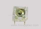


Yellow White light emitting diode led Chip material AlGaInP InGaN Square With 5mm Dome 4 Lead
LED Light Emitting Diode
- Features:
- Automotive exterior lighting.
- Electronic signs and signals.
- Special lighting application.
-
- Applications:
- This revolutionary package design allows the light designer to reduce the number of LEDs required and provide a more uniform and unique illuminated appearance than with other LED solutions.
- The low profile package can be easily coupled with reflectors or lenses to efficiently distribute light and provide the desired light appearance.
-
- Descriptions:
- Fewer LEDs required.
- Low profile.
- Lowers lighting system cost.
- Super flux output.
- Viewing angle=70°.
- The product itself will remain within RoHS compliant Version.
| Part No. | Chip Material | Lens Color | Source Color |
| DL-U50-2UYW45 | AlGaInP | Water Clear | Super Yellow |
- Reliability Test
-
Classification Test Item Reference Standard Test Conditions Result Endurance Test
Operation Life MIL-STD-750:1026
MIL-STD-883:1005
JIS-C-7021 :B-1
Connect with a power If=20mA
Ta=Under room temperature
Test time=1,000hrs
0/20
High Temperature
High Humidity
Storage
MIL-STD-202:103B
JIS-C-7021 :B-11
Ta=+65±5
RH=90%-95%
Test time=240hrs
0/20
High Temperature
Storage
MIL-STD-883:1008
JIS-C-7021 :B-10
High Ta=85±5
Test time=1,000hrs 0/20
0/20
Low Temperature
Storage
JIS-C-7021 :B-12
Low Ta=-35±5
Test time=1,000hrs
0/20
Environmental Test
Temperature Cycling MIL-STD-202:107D
MIL-STD-750:1051
MIL-STD-883:1010
JIS-C-7021 :A-4
-35 ~ +25 ~ +85 ~ +25
60min 20min 60min 20min
Test Time=5cycle
0/20
Thermal Shock MIL-STD-202:107D
MIL-STD-750:1051
MIL-STD-883:1011
35±5 ~+85±5
20min 20min
Test Time=10cycle
0/20
Solder Resistance MIL-STD-202:201A
MIL-STD-750:2031
JIS-C-7021 :A-1
Preheating:
140-160, within 2 minutes.
Operation heating: 235 (Max.), within 10seconds (Max.)
0/20
- Judgment criteria of failure for the reliability
-
Measuring items Symbol Measuring conditions Judgment criteria for failure Forward voltage VF (V) IF=20mA Over Ux1.2 Reverse current IR(uA) VR=5V Over Ux2 Luminous intensity Iv (mcd) IF=20mA Below SX0.5 - Absolute Maximum Ratings at Ta=25
| Parameters | Symbol | Max. | Unit | |
| Power Dissipation | Yellow | PD | 45 | mW |
| White | 70 | |||
|
Peak Forward Current (1/10 Duty Cycle, 0.1ms Pulse Width) |
IFP | 160 | mA | |
| Chip Forward Current | IF | 30 | mA | |
| Reverse Voltage | VR | 5 | V | |
| Operating Temperature Range | Topr | -40 to +85 | ||
| Storage Temperature Range | Tstg | -40 to +100 | ||
|
Lead Soldering Temperature [4mm (.157″) From Body] |
Tsld | 260 for 5 Seconds | ||


