- Minimal leakage current suitable for medical equipment
- Two element circuit provides basic EMI attenuation above 1 MHz
- Available with an internal ground circuit inductor
(C suffix versions) to isolate equipment chassis from
power line ground at radio frequencies - Flanged mounting the same as the EC, ED and EF Series
- Capacitive output (see EAH, EBH and EJH Series for capacitive input)
Ordering Information
Available Part Numbers
Electrical Schematic
H3 (Chassis Mount)
H4 & H4C
H9
H5
H8
Recommended Panel Cutouts

Available Part Numbers
3EH1 | 6EH8 |
3EH3 | 6EH9 |
6EH1 | 10EH1 |
6EH3 | 10EH3 |
6EH4 | 10EH4 |
6EH5 | 15EH4 |
GroundCircuit Inductor Versions | |
10EH4C | |
Specifications
| Maximum leakagecurrent, each Line to Ground: | ||
| @ 120 VAC 60 Hz | 2 µA | |
| @ 250 VAC 50 Hz | 5 µA | |
| Hipot rating (oneminute): | ||
| Line to Ground | 2250 VDC | |
| Line to Line | 1450 VDC | |
| Operating Frequency: | 50 / 60 Hz | |
| Rated voltage(max.): | 250 VAC | |
| Rated Current: | 3A to 15A | |
| Operating Ambient Temperature Range(at rated current Ir): | ||
-10°C to +40°C | ||
In an ambienttemperature (Ta) higher than +40°C the maximum operating current (Io) is calculated as follows: Io = Ir √(85-Ta)/45 | ||
Electrical Schematic

Accessories
GA400: NEMA 5-15P to IEC 60320-1 C13 line cord
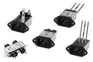
Case Styles
H1 (Chassis Mount)

Case Styles
H1 (Chassis Mount)

| Typical Dimensions: | ||
| Mounting holes (2): | .188 [4.78] Dia. | |
| Line/Load Terminals (4): | .250 [6.35] with .07 [1.8] Dia. hole | |
| Ground Terminal (1): | .250 [6.35] with .07 x .16 [1.8 x 4.1] slot | |
H3 (Chassis Mount)

| Typical Dimensions: | ||
| Mounting holes (2): | .188 [4.78] Dia. | |
| Wire Leads (5): | 4.0 [101.6] Min., 18AWG, UL1015 | |
H4 & H4C

| Typical Dimensions: | ||
| Mounting holes (2): | .132 [3.35] Dia. | |
| Line Inlet (1): | IEC 60320-1 C14 | |
| Load Terminals (2): | .250 [6.35] with .07 [1.8] Dia. hole | |
| Ground Terminal (1): | .250 [6.35] with .07 x .16 [1.8 x 4.1] slot | |
H9

| Typical Dimensions: | ||
| Mounting holes (2): | .132 [3.35] Dia. | |
| Line Inlet (1): | IEC 60320-1 C14 | |
| Load Terminals (2): | .250 [6.35] with .07 [1.8] Dia. hole | |
| Ground Terminal (1): | .250 [6.35] with .07 x .16 [1.8 x 4.1] slot | |
H5

| Typical Dimensions: | ||
| Mounting holes (2): | .132 [3.35] Dia. | |
| Line Inlet (1): | IEC 60320-1 C14 | |
| Wire Leads: | 4.0 [101.6] Min., 18AWG, UL1015 | |
H8

| Typical Dimensions: | ||
| Mounting holes (2): | .132 [3.35] Dia. | |
| Line Inlet (1): | IEC 60320-1 C14 | |
| Wire Leads: | 4.0 [101.6] Min., 18AWG, UL1015 | |
Recommended Panel Cutouts

Case Dimensions
| Part No. | A | B | C | D | E | F |
(max.) | (max.) | (max.) | ±.015 | (max.) | (ref..) | |
± .38 | ||||||
| H1 | 2.25 | 1.82 | 0.66 | 2.125 | 2.53 | |
57.2 | 46.1 | 16.7 | 53.98 | 64.2 | ||
| H3 | .96 | 1.82 | 0.66 | 2.125 | 2.53 | |
24.40 | 46.1 | 16.7 | 53.98 | 64.2 | ||
| 6EH4 | 2.20 | 1.19 | 0.81 | 1.575 | 1.98 | |
55.9 | 30.2 | 20.6 | 40.01 | 50.3 | ||
| 10EH4, 10EH4C | 2.62 | 1.19 | 0.81 | 1.575 | 1.98 | |
66.5 | 30.2 | 20.6 | 40.01 | 50.3 | ||
| 15EH4 | 2.62 | 1.19 | 0.81 | 1.575 | 1.98 | |
66.5 | 30.2 | 20.6 | 40.01 | 50.3 | ||
| H5 | 1.55 | 1.19 | 0.85 | 1.575 | 1.98 | .295 |
39.4 | 30.2 | 21.6 | 40.01 | 50.3 | 7.5 | |
| H8 | 1.56 | 1.19 | 0.81 | 1.575 | 1.98 | .295 |
39.7 | 30.2 | 20.6 | 40.01 | 50.3 | 7.5 | |
| H9 | 1.55 | 1.19 | 0.85 | 1.575 | 1.98 | |
39.4 | 30.2 | 21.6 | 40.01 | 50.3 | ||
Performance Data
Typical Insertion Loss
Measured in closed 50 ohm system
3EH
6EH
10EH
15EH

Minimum Insertion Loss in dB:
Measured in closed 50 ohm system
Common Mode / Asymmetrical (Line to Ground)
Typical Insertion Loss
Measured in closed 50 ohm system
3EH

6EH

10EH

15EH


Minimum Insertion Loss in dB:
Measured in closed 50 ohm system
Common Mode / Asymmetrical (Line to Ground)
| Current Rating | Frequency - MHz | |||||
.15 | .5 | 1 | 5 | 10 | 30 | |
3A | 18 | 27 | 30 | 30 | 27 | 18 |
6A | 9 | 16 | 20 | 26 | 23 | 18 |
10A | 7 | 13 | 15 | 17 | 16 | 14 |
15A | 5 | 9 | 11 | 12 | 11 | 9 |


