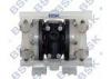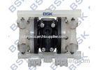


No-leakage Polypropylene Diaphragm Pump For Printing Ink / Dyeing
Air diaphragm pump(also know as a Membrane pump, air operated double diaphragm pump(AOOD) or pneumatic diaphragm pump)that uses a combination of the reciprocating action of a rubber,thermoplastic or teflondiaphragm and suitable valves either side of the diaphragm (check valve,butterfly valves,flap valves,or any other form of shut-off valves) to pump a fluid.

Poly Phenylene Pneumatic Diaphragm Pump For Spray Paint &ink & Oil &Pharmacy
Product Description:
| Air Inlet | 1/4-18NPTF-1 |
| Fluid Outlet | 1-1/4-18NPTF-1 |
| Fluid Inlet | 1-1/4-18NPTF-1 |
| Max. Flow | 35L/Min |
| Max. Head | 27M |
| Max. Self-priming Lift (dry) | 4.5m |
| Max. Air Pressure | 8.3bar |
| Max. Particle Diameter | 1mm |
| Max. Installation Dimension | 195×162×120mm |
| Weight | 1.5kg |
| Noise | <80db |
Application& Specifications
The pump can suck various strong acid, alkali and corrosive liquid etc.
General Description The BSK diaphragm pump offers high volume delivery even at low air pressure and a b road range of material compatibility options available.Refer to the model and option chart.The BSK pump is provided with the modularized air motor and fluid section. The air operated diaphragm pump alternately generates the intake fluid pressure and positive fluid pressure in the fluid chamber by using the pressure difference in the air chamber. The ball valve can ensure the forward flow of fluid. Pump cycling will begin as air pressure is applied and it will continue to pump and keep up with the demand. It will build and maintain line pres -sure and will stop cycling once maximum line pressure is reached (dis -pensing device closed) and will resume pumping as needed. Requirements for Air and Lubrication
EXCESSIVE AIR PRESSURE. Can cause pump damage, personal injury or property damage.
A filter capable of filtering out particles larger than 50 microns should be used on the air supply. There is no lubrication required other than the “O” ring lubricant which is applied during assembly or repair. If lubricated air is present, make sure that it is compatible with the “O” rings and seals in the air motor section of the pump. OPERATING INSTRUCTIONS Always flush the pump with a solvent compatible with the material being pumped if the material being pumped is subject to “setting up” when not in use for a period of time. Disconnect the air supply from the pump if it is to be inactive for a few hours. The outlet material volume is governed not only by the air supply but also by the material supply available at the inlet. The material supply tubing should not be too small or restrictive. Be sure not to use hose which might collapse.
When the diaphragm pump is used in a forced -feed (flooded inlet) situation, it is recommended that a “Check Valve” be installed at the air inlet. Secure the diaphragm pump legs to a suitable surface to insure against damage by vibration. Maintenance Please refer to the component schematic in the assembly drawings to look up the serial numbers and names of parts and grasp the information of parts and maintenance service pack. Some BSK parts are marked as "wearing parts", which can conduce to quick service and downtime reduction. Service kits are divided to service two separate diaphragm pump functions: 1. AIR SECTION, 2. FLUID SECTION. The FLUID SEC -TION is divided further to match typical part MATERIAL OPTIONS.
Provide a clean work surface to protect sensitive internal moving parts from contamination from dirt and foreign matter during service disassembly and reassembly. Keep good records of service activity and include pump in preven -tive maintenance program. Before disassembling, empty captured material in the outlet man -ifold by turning the pump upside down to drain material from the pump. FLUID SECTION DISASSEMBLY Remove the upper and lower manifold (1) and (11). Remove the ball (2), “O” ring (3) (47) and ball seat (4). Remove the fluid cap (5). NOTE: Only diaphragm models use a primary diaphragm(6A) and a backup diaphragm(6). Refer to the aux iliary view in the Fluid Section illustration. Remove the screw (10), washer (9), diaphragm (6A, 6) and diaphragm washer (7, 8).
NOTE: Do not scratch or mar the surface of (23) diaphragm rod. FLUID SECTION REASSEMBLY Reassemble in reverse order. Clean and inspect all parts. Replace worn or damaged parts with new parts as required. Lubricate (23) diaphragm rod and 25) “Y” ring with grease. Fix the diaphragm rod (23) with the auxiliary installation tool. Prior to the final fastening of bolts and nuts, please determine whether the diaphragm (6A,6) is aligned with the fluid cap (5) properly to avoid the twisting of the diaphragm. For the models using Teflon diaphragm: three rubber diaphragms (6) on the side, which are marked with AIRS SIDE "air chamber" are mounted in face of the pump body. Start the pump, check the fastening and sealing after it runs for a period of time.
Flow rate:

Maintenance
Please refer to the component schematic in the assembly drawings to look up the serial numbers and names of parts and grasp the information of parts and maintenance service pack. Some BSK parts are marked as "wearing parts", which can conduce to quick service and downtime reduction. Service kits are divided to service two separate diaphragm pump functions: 1. AIR SECTION, 2. FLUID SECTION. The FLUID SEC -TION is divided further to match typical part MATERIAL OPTIONS. Provide a clean work surface to protect sensitive internal moving parts from contamination from dirt and foreign matter during service disassembly and reassembly. Keep good records of service activity and include pump in preven -tive maintenance program. Before disassembling, empty captured material in the outlet man -ifold by turning the pump upside down to drain material from the pump.
FLUID SECTION DISASSEMBLY
Remove the upper and lower manifold (1) and (11).
Remove the ball (2), “O” ring (3) (47) and ball seat (4).
Remove the fluid cap (5). NOTE: Only diaphragm models use a primary diaphragm(6A) and a backup diaphragm(6). Refer to the aux iliary view in the Fluid Section illustration.
Remove the screw (10), washer (9), diaphragm (6A, 6) and diaphragm washer (7, 8). NOTE: Do not scratch or mar the surface of (23) diaphragm rod. FLUID SECTION REASSEMBLY
Reassemble in reverse order.
Clean and inspect all parts. Replace worn or damaged parts with new parts as required.
Lubricate (23) diaphragm rod and 25) &