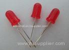


Ultra brightness DIP red light emitting diode 60 Deg 400*340*345cm
- Features:
- Popular T-1 3/4 diameter package.
- High efficiency.
- Selected minimum intensities.
- Available on tape and reel.
- Reliable and robust.
- The product itself will remain within RoHS compliant Version.
- Descriptions:
- The series is specially designed for applications requiring higher brightness.
- The LED lamps are available with different colors, intensities.
- Applications:
- TV set.
- Monitor.
- Telephone.
- Computer.
- Circuit board.
- Status indicators.
- Commercial use.
- Advertising Signs.
- Back lighting.
Package Dimensio:
| Part No. | Chip Material | Lens Color | Source Color |
| DL-503SRDA-1SR30 | GaAlAs | Red Diffused | ultra Red |
Notes:
- All dimensions are in millimeters (inches).
- Tolerance is ± 0.25 mm (.010″) unless otherwise noted.
- Protruded resin under flange is 1.00 mm (.04″) max
- Specifications are subject to change without notice.
- Absolute Maximum Ratings at Ta=25
-
Parameters Symbol Max. Unit Power Dissipation PD 78 mW Peak Forward Current
(1/10 Duty Cycle, 0.1ms Pulse Width)
IFP 100 mA Forward Current IF 30 mA Reverse Voltage VR 5 V Operating Temperature Range Topr -40 to +85 Storage Temperature Range Tstg -40 to +100 Lead Soldering Temperature
[4mm (.157″) From Body]
Tsld 260 for 5 Seconds Electrical Optical Characteristics at Ta=25
Parameters Symbol Min. Typ. Max. Unit Test Condition Luminous Intensity
(Note 1)*
IV 450 700 --- mcd IF=20mA Viewing Angle* 2θ1/2 --- 30 --- Deg (Note 2) Peak Emission Wavelength λp --- 630 --- nm IF=20mA Dominant Wavelength λd --- 619 --- nm IF=20mA Spectrum Radiation Bandwidth Δλ --- 20 --- nm IF=20mA Forward Voltage VF 1.60 2.20 2.60 V IF=20mA Reverse Current IR --- --- 10 µA VR=5V Notes:
- Luminous Intensity Measurement allowance is ± 10%.
- θ1/2 is the off-axis angle at which the luminous intensity is half the axial luminous intensity.
-
- Typical Electrical / Optical Characteristics Curves
-
(25 Ambient Temperature Unless Otherwise Noted)

- Reliability Test Items And Conditions:
-
The reliability of products shall be satisfied with items listed below:
Confidence level: 90%. LTPD: 10%.
- Test Items and Results:
-
Test Item Standard Test Method Test Conditions Note Number of Damaged Resistance to Soldering Heat JEITA ED-4701
300 302
Tsld=260±5, 10sec 3mm from the base of the epoxy bulb 1 time 0/100 Solder ability JEITA ED-4701
300 303
Tsld=235±5, 5sec(using flux) 1time
over 95%
0/100 Thermal Shock JEITA ED-4701
300 307
0~100 15sec, 15sec 100 cycles 0/100 Temperature Cycle JEITA ED-4701
100 105
-40~25~100~25 30min,5min,30min,5min 100 cycles 0/100 Moisture Resistance Cylix JEITA ED-4701
200 203
25~65~-10 90%RH 24hrs/1cycle 10 cycles 0/100 High Temperature Storage JEITA ED-4701
20
Didn't find what you're looking for? Post Buying Lead or contact our customer service specialist for help!About HiSupplier
User Guide
Featured Partners:

 Browse by: China Suppliers - Hot Products - Products Directory - Offers Directory - Suppliers Directory - Buyers DirectoryFollow Us:

Channel: madeinchina.hisupplier.com - hebei.hisupplier.com - ningbo.hisupplier.com
Language Option: العربية - Nederlands- Français- Deutsch- Italiano- 日本語- 한국의- Português- Pусский- Español
IPR Protection Policy - Terms of Use - Privacy Policy - Security Measures
Copyright © HiSupplier.com Online Inc. All Rights Reserved.

