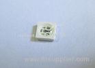


Pure Green brightest led chip 3528 Rgb SMD LED 0.1 watt 515 - 525nm
- Features:
- P-LCC-2 package.
- White package.
- Optical indicator.
- Colorless clear window.
- Ideal for backlight and light pipe application.
- Inter reflector.
- Wide viewing angle.
- Suitable for automatic placement equipment.
- Suitable for vapor-phase reflow, Infrared reflow and wave solder processes.
- Available on tape and reel (8mm Tape).
- The product itself will remain within RoHS compliant Version.
- Descriptions:
- The BL-TOP3528 series is available in soft red, orange, yellow, green, blue and white. Due to the package design, the LED has wide viewing angle and optimized light coupling by inter reflector. This feature makes the SMT TOP LED ideal for light pipe application. The low current requirement makes this device ideal for portable equipment or any other application where power is at a premium.
- Applications:
- Automotive: Backlighting in dashboards and switches.
- Telecommunication: Indicator and backlight in telephone and fax
- Indicator and backlight for audio and video equipment.
- Indicator and backlight in office and family equipment.
- Flat backlight for LCD’s, switches and symbols.
- Light pipe application.
- General use.
- Package Dimension:

-
Parameters Symbol Max. Unit Power Dissipation PD 95 mW Peak Forward Current
(1/10 Duty Cycle, 0.1ms Pulse Width)
IFP 100 mA Continuous Forward Current IF 25 mA Reverse Voltage VR 5 V Electrostatic Discharge (HBM) ESD 1000 V Operating Temperature Range Topr -40 to +80 Storage Temperature Range Tstg -40 to +85 Soldering Temperature Tsld 260 for 5 Seconds Electrical Optical Characteristics at Ta=25
Parameters Symbol Min. Typ. Max. Unit Test Condition Luminous Intensity * IV 550 1000 --- mcd IF=20mA (Note 1) Viewing Angle * 2θ1/2 --- 120 --- Deg IF=20mA (Note 2) Peak Emission Wavelength λp --- 520 --- nm IF=20mA Dominant Wavelength λd --- 525 --- nm IF=20mA (Note 3) Spectral Line Half-Width λ --- 35 --- nm IF=20mA Forward Voltage VF 3.00 3.30 3.80 V IF=20mA Reverse Current IR --- --- 10 µA VR=5V Notes:
- Luminous Intensity Measurement allowance is ± 10%.
- θ1/2 is the off-axis angle at which the luminous intensity is half the axial luminous intensity.
-
The dominant wavelength (λd) is derived from the CIE chromaticity diagram and represents the single wavelength which defines the color of the device.
- Typical Electrical / Optical Characteristics Curves
-
(25 Ambient Temperature Unless Otherwise Noted)
CIE Chromaticity Diagram:
-

- Reliability Test Items And Conditions:
-
The reliability of products shall be satisfied with items listed below:
Confidence level: 90%.
LTPD: 10%.
1) Test Items and Results:
No. Test Item Test Hours/Cycles Test Conditions Sample Size Ac/Re 1 Resistance to Soldering Heat 6 Min Tsld=260±5,
Min. 5sec
25pcs 0/1 2 Thermal Shock 300 Cycles H: +100 5min ∫ 10 sec
L: -10 5min
25pcs 0/1 3 Temperature Cycle 300 Cycles H: +100 15min ∫ 5min
L: -40 15min
25pcs 0/1 4 High Temperature Storage 1000Hrs. Temp: 100 25pcs 0/1 5 DC Operating Life 1000Hrs. IF=20mA 25pcs 0/1 6 Low Temperature Storage 1000Hrs. Temp: -40 25pcs 0/1 7 High Temperature/ High Humidity 100
Didn't find what you're looking for? Post Buying Lead or contact our customer service specialist for help!About HiSupplier
User Guide
Featured Partners:

 Browse by: China Suppliers - Hot Products - Products Directory - Offers Directory - Suppliers Directory - Buyers DirectoryFollow Us:

Channel: madeinchina.hisupplier.com - hebei.hisupplier.com - ningbo.hisupplier.com
Language Option: العربية - Nederlands- Français- Deutsch- Italiano- 日本語- 한국의- Português- Pусский- Español
IPR Protection Policy - Terms of Use - Privacy Policy - Security Measures
Copyright © HiSupplier.com Online Inc. All Rights Reserved.

