

SMD 3528 Height Top View Infrared Chip LED 940nm Infrared Emitting Diode Radiant Intensity 7.0mW/sr
3528 Infrared Emitting Diode
- Features:
- PCB mounted infrared sensor.
- Infrared emitting for miniature light barrier.
- Floppy disk drive.
- Optoelectronic switch.
- Smoke detector.
- Camera.
- VCR.
- Video.
-
- Applications:
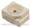
- The 3528 is an infrared emitting diode in miniature SMD package which is molded in a water clear epoxy with flat top view lens.
- The device is specially matched with photodiode, phototransistor and infrared receiver module.
-
- Descriptions:
- Package in 8mm tape on 7” diameter reel.
- P-LCC-2 package.
- White package.
- Optical indicator.
- Colorless clear window.
- Low forward voltage.
- Wide viewing angle.
- Suitable for automatic placement equipment.
- Suitable for vapor-phase reflow, infrared reflow solder processes.
- The product itself will remain within RoHS compliant Version.
- Absolute Maximum Ratings at Ta=25
| Parameters | Symbol | Max. | Unit |
| Power Dissipation | PD | 130 | mW |
|
Peak Forward Current (1/10 Duty Cycle, 0.1ms Pulse Width) |
IFP | 1.00 | A |
| Continuous Forward Current | IF | 65 | mA |
| Reverse Voltage | VR | 5 | V |
| Operating Temperature Range | Topr | -25 to +80 | |
| Storage Temperature Range | Tstg | -40 to +85 | |
| Soldering Temperature | Tsld | 260 for 5 Seconds | |
Electrical Optical Characteristics at Ta=25
| Parameters | Symbol | Min. | Typ. | Max. | Unit | Test Condition |
| Radiant Intensity * | Ee | 1.00 | 1.50 | --- | mW/sr | IF=20mA |
| --- | 7.00 | --- |
IF=100mA (Pulse Width≤100µs, Duty≤1%) |
|||
| Viewing Angle * | 2θ 1/2 | --- | 120 | --- | Deg | IF=20mA (Note 2) |
| Peak Emission Wavelength | λp | --- | 940 | --- | nm | IF=20mA (Note 3) |
| Spectral Bandwidth | λ | --- | 45 | --- | nm | IF=20mA |
| Forward Voltage | VF | 0.80 | 1.20 | 1.50 | V | IF=20mA |
| --- | 1.40 | 1.80 |
IF=100mA (Pulse Width≤100µs, Duty≤1%) |
|||
| Reverse Current | IR | --- | --- | 10 | µA | VR=5V |
Notes:
Luminous (Radiant) Intensity Measurement allowance is ± 10%. θ1/2 is the off-axis angle at which the luminous intensity is half the axial luminous intensity. The dominant wavelength (λp) is derived from the CIE chromaticity diagram and represents the single wavelength which defines the color of the device.
Infrared Emitting Diode Package Dimension:


