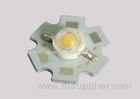


1W High Power Red Color LED Light Components 35 - 45lm 620 - 630nm 640-660nm for Plant grow lighting
1W High Power Red Color LED
Precautions for Use:
1. Over-current-proof
Customer must not use the device in reverse and should apply resistors for extra protection. Otherwise slight voltage shift may cause abnormal current change and burn out failure would happen.
2. Storage
Do not open moisture proof bag before the products are ready to be used.
Before opening the package, the LEDs should be kept at 30 or less and 90%RH or less.
The LEDs should be used within a year.
After opening the package, the LEDs should be kept at 30 or less and 70%RH or less.
The LEDs should be used within 168 hours (7 days) after opening the package.
If the moisture absorbent material (silicone gel) has faded away or the LEDs have exceeded the storage time, baking treatment should be performed using the following conditions:
Pre-curing treatment: 60±5 for 24 hours.
3. Thermal Management
Because HP60M LED is a high power dissipation device, special and sufficient consideration in thermal management design must be made to optimize the thermal performance.
Heat sink design is implemented in the device for an additional thermal connection. Since the device is capable of SMT process, tin must be spread both heat sink and solder pads areas to dissipate the heat.
A high thermal conductivity substrate, such as Aluminum or Copper plate etc, must be applied for external thermal management. It is strongly recommended that the outer heat sink or PCB dimension per LED can not be less than 25 x 25 x 1 (L x W x H) mm. The materials for outer heat sink can be FR4 on Aluminum, MCPCB, or FPC on Aluminum.
Special thermal designs are also recommended to take in outer heat sink design, such as FR4 PCB on Aluminum with thermal vias or FPC on Aluminum with thermal conductive adhesive, etc.
Sufficient thermal management must be conducted, or the die junction temperature will be over the limit under large electronic driving and LED lifetime will decrease critically.
4. Soldering Condition
Soldering should not be done more than two times.
While soldering, do not put stress on the LEDs during heating.
After soldering, do not warp the circuit board.
5. Soldering Iron
For prototype builds or small series production runs it is possible to place and solder the LED by hand.
Dispensing thermal conductive glue or grease on the substrates and follow its curing spec. Press LED housing to closely connect LED and substrate.
It is recommended to hand solder the leads with a solder tip temperature of 280°C for less than 3 seconds within once in less than the soldering iron capacity 25W. Leave two seconds and more intervals, and do soldering of each terminal.
Be careful because the damage of the product is often started at the time of the hand solder.
6. Handling Indications
During processing, mechanical stress on the surface should be minimized as much as possible. Sharp objects of all types should not be used to pierce the sealing compound.
Absolute Maximum Ratings at Ta=25
| Parameters | Symbol | Rating | Units |
| Forward Current | IF | 350 | mA |
| PeakPulseCurrent (tp≤100μs, Duty cycle=0.25) | I pulse | 500 | mA |
| Reverse Voltage | VR | 5 | V |
| LED Junction Temperature | Tj | 125 | |
| Operating Temperature Range | Topr | -40 to +80 | |
| Storage Temperature Range | Tstg | -40 to +100 | |
| Soldering Time at 260 (Max.) | Tsol | 5 | Seconds |
Notes:
1. Proper current derating must be observed to maintain junction temperature below the maximum.
2. LEDs are not designed to be driven in reserve bias.
Electrical Optical Characteristics at Ta=25
| Parameters | Symbol | Min. | Typ. | Max. | Unit | Test Condition |
| Viewing Angle [1] | 2θ1/2 | --- | 140 | -- | Deg | IF=350mA |
| Forward Voltage [2] | VF | 2.0 | 2.20 | 3.00 | V | IF=350mA |
| Reverse Current | IR | --- | --- | 10 | µA | VR=5V |
| Peak Emission Wavelength | λp | --- | 632 | --- | nm | IF=350mA |
| Dominant Wavelength | λd | --- | 624 | --- | nm | IF =350mA |
| Spectrum Radiation Bandwidth | Δλ | --- | 18 | --- | nm | IF=350mA |
| Luminous Flux | v | 25 | 30 | --- | lm | IF=350mA |
Notes:
1. 2θ1/2 is the off axis angle from lamp centerline where the luminous intensity is 1/2 of the peak value. 2. Forward Voltage measurement tolerance: ±0.1V


